
Product / Model
Dimension-driven models. Human-editable history.
Chudware models are dimension-driven. A fully defined sketch — relations first, then driving dimensions — becomes an exact solid through a feature, and the Feature Manager keeps every step human-editable for the life of the design. Change a dimension and the part rebuilds in order.
The workspace
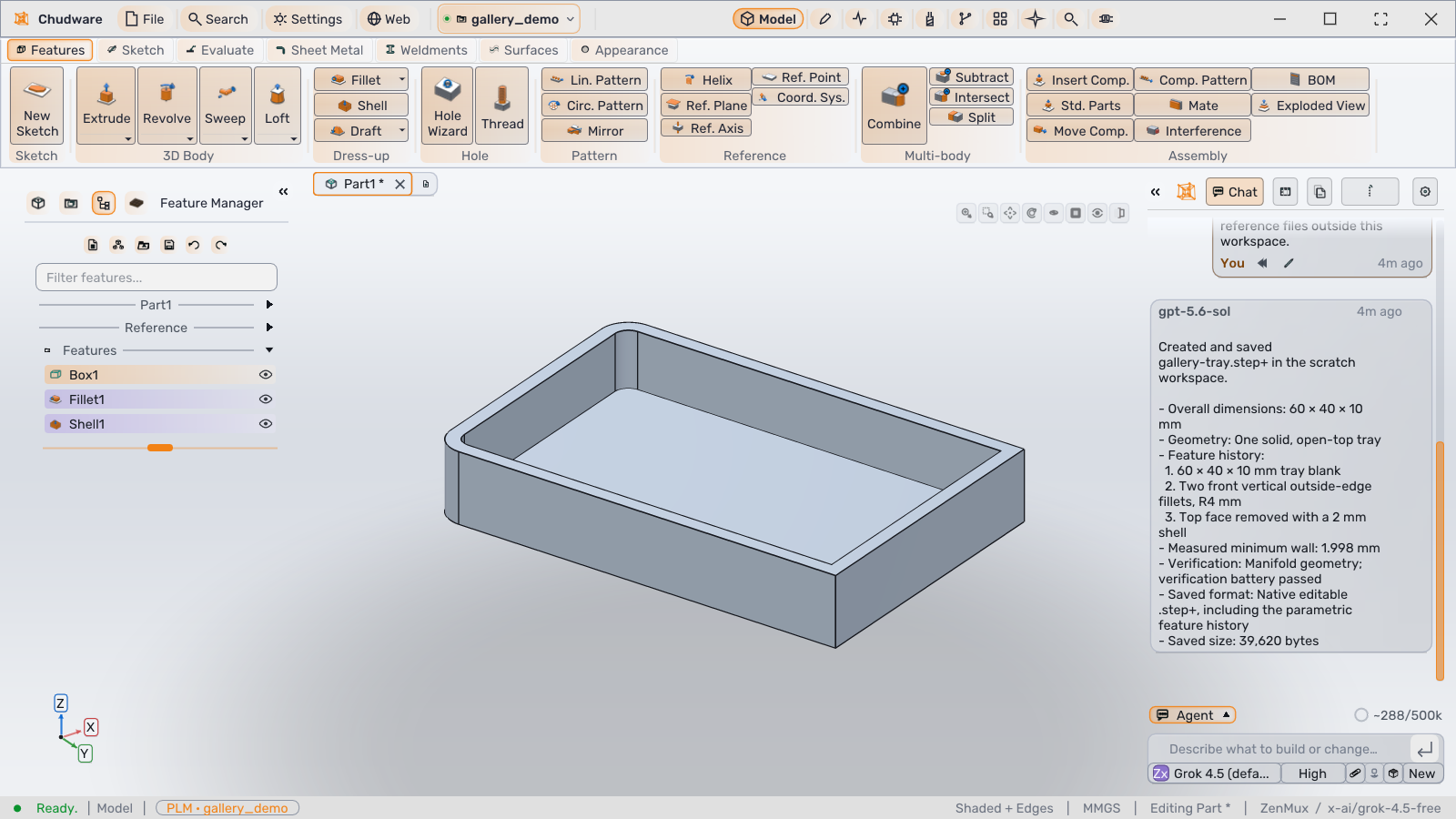
The model and its history, side by side.
Features are never baked away. A box, a fillet, and a shell stay listed in order next to the model, and any of them can be reopened, re-dimensioned, or reordered.
Saving as .step+ keeps the feature tree, dimensions, materials, studies, and drawings in one editable document. Neutral exports exist for handing a flattened result to another tool, not for storing your design.
Feature history
Change one dimension. The whole part rebuilds in order.
Editing a sketch dimension recomputes the downstream extrude, boss, fillet, holes, and pockets in order.
Feature sequence · illustration
Constraint sketching
Constrain intent, not the picture.
Start with relations — coincident, horizontal, vertical, parallel, perpendicular, tangent, concentric, collinear, equal, midpoint, symmetric, fix — then add only the dimensions that set size and position. The sketch status reports remaining degrees of freedom and flags conflicting constraints, so an under-defined profile is visible rather than surprising.
Where a part is naturally symmetric, reference the origin and construction geometry and mirror half the profile. That is more stable than dimensioning two nearly identical sides. If a sketch becomes over-defined, remove the newest redundant relation instead of suppressing the warning.
The modeling loop
How a part actually gets built.
The same six steps cover the first bracket and the hundredth revision of it.
Start a document with a real name
Create a part and name it for what it is, such as
mounting-bracket. Revision numbers belong in project history, not in the filename.Sketch on a plane
Pick a reference plane, draw the profile, and keep each sketch focused. Several small sketches are easier to revise than one drawing that controls the entire part.
Add relations, then dimensions
Apply horizontal, vertical, and coincident relations, then use Smart Dimension for the values that matter. A fully defined sketch cannot drift when an upstream dimension changes.
Choose the feature the profile implies
A closed planar profile extrudes or revolves. Cross-sections on several planes loft. A profile following a path sweeps. Repeated geometry is built once and patterned.
Refine on the solid
Select edges or faces and apply Fillet, Chamfer, Shell, Draft, or Rib. If a preview fails, reduce the radius or check whether the selected edges meet a very short face.
Save an editable design
Save as
.step+so the tree, dimensions, materials, studies, and drawings travel with the geometry. Export a neutral format only for a downstream handoff.
Drawings
The sheet lives in the same document as the model.
A drawing is not a side file that quietly goes stale. Sheets are stored inside the .step+ document, and every view is re-projected from the current solid each time the sheet is opened, so a dimension change upstream cannot leave the drawing disagreeing with the part.
- ViewsModel, projected, standard three, section — including half section — and detail views, each at its own scale.
- DimensionsSmart dimensions, model items pulled from the feature tree, hole callouts, center marks, center lines, notes, and balloons.
- TolerancingPer-dimension symmetric, deviation, limit, or basic tolerance at zero to four decimal places, plus ASME Y14.5 feature control frames — all fourteen geometric characteristics, with material-condition modifiers — datums, datum targets, surface finish, and weld symbols.
- Sheets and tablesISO A4 to A0 and ANSI A to E sheet sizes, an editable title block, and a bill of materials rolled up from the assembly — identical components grouped with quantities, pattern instances already counted.
Output
Drawings export to DXF and PDF. Those are the only two formats the export path accepts, and it rejects anything else rather than writing a file that looks plausible. A sheet-metal part flattens to its own DXF with the outline and the bend lines on separate layers.
Specifics
What's in the modeling workspace.
Chudware models are dimension-driven on exact solid geometry: fillets, holes, and reference faces are analytic surfaces, not display triangles. A 2D constraint solver fully defines sketches, and the feature tree keeps construction order human-editable. The browser workspace and the desktop app share the same modeling tools.
View control stays out of the way: F fits the model, 0 returns to isometric, and the numbered keys jump to standard views while a command is running.
| Geometry | Exact B-rep solids — analytic faces, not a triangle mesh |
|---|---|
| Sketch relations | Coincident, horizontal, vertical, parallel, perpendicular, tangent, concentric, collinear, equal, midpoint, symmetric, fix; linear and angular dimensions |
| Sketch feedback | Remaining degrees of freedom and conflicting-constraint reporting |
| Profile features | Extrude, Revolve, Sweep, Loft — each as a boss or a cut |
| Dress-up features | Fillet, Chamfer, Shell, Draft, Rib |
| Holes and threads | Hole Wizard, plus ISO and Unified threads on a selected cylindrical face |
| Patterns | Linear, circular, mirror |
| Multi-body | Combine, subtract, intersect, split |
| Reference geometry | Planes, axes, points, coordinate systems, helix curves |
| Surfaces | Extruded, revolved, swept, lofted, planar, offset, ruled, boundary; knit, thicken, trim |
| Sheet metal | Base flange, edge flange, hem, jog, flat pattern with layered DXF output |
| Weldments | Structural members swept along a path sketch, gussets, end caps |
| Drawings | Multi-view sheets with dimensions, ASME Y14.5 geometric tolerancing, title block, and BOM; DXF and PDF output |
| Units | Millimeter or inch per document; geometry is stored in millimeters either way, so switching units never rescales a part |
| History | Ordered Feature Manager tree, human-editable after the fact |
| Native format | .step+ — tree, dimensions, materials, studies, drawings |
| Import | STEP, IGES, and BREP solids; STL, OBJ, PLY, and glTF meshes; DXF for 2D profiles |
| Neutral export | STEP, IGES, BREP, STL, OBJ, PLY, glTF for downstream handoff |
Next
Model it, then take it downstream.
Open a workspace in the browser, or see how the same document carries into assemblies and CAM.